Technical and tactical specifications of the MVN-72 fuze
- Fuze type
- non-contact magnetic
- Fuze weight
- 1.15 kg
- Explosive weight
- 10 g
- Explosive type
- Tetryl
- Diameter
- 125 mm
- Height
- 96 mm
- Arming-delay mechanism type
- clockwork
- Arming-delay time
- 30-120 s
- Operational service time
- 1 month
- Operating temperature range
- -40 to +50 °C
- Power source
- PMC-U-48ch cell (KB-U-1.5)
- Method of emplacement
- manual
- Guaranteed storage life
- 5 years (without power source)
- Color
- dark green
Design and operating principle of the MVN-72 fuze
The MVN-72 fuze consists of a body, inside which a clockwork arming-delay mechanism (with elements of the firing train) and a non-contact magnetic sensor are located.

The body (item 1) is made of aluminum alloy. On the top of the body there is a shaped recess in which the following are located: a button (item 8) for starting the clockwork arming-delay mechanism; a folding handle (item 2) for winding the spring of the clockwork mechanism and switching the fuze from the armed position to the transport position; a safety pin (item 6) for securing the button and handle in the transport position. The folding handle has two ribs with holes for installing the cotter pin (item 4) and wire with seal (item 3); and a cylindrical lug (item 5) for securing the safety pin.
The safety pin (item 6) is made in the form of a rigid steel plate with a cut-out, installed under the button. A latch with a hole (which fits over the handle lug when the pin is installed) and a leaf spring are riveted to the plate. During depot storage, the safety pin is secured with a cotter pin (item 4) and sealed.
On the top of the fuze body there are two slots for the pins of the wrench (Fig. 3, b), by which the fuze is screwed into the mine. An arrow is also marked on the body, indicating the direction of rotation of the handle when winding the spring of the clockwork mechanism, as well as a diagram for installing the power source. On the side of the fuze body there is a socket for the power source, closed by a threaded plug (item 7). A slot for the wrench (Fig. 3, a), by which the plug is unscrewed (or tightened), is machined into the plug. The lower part of the body has an external thread for screwing the fuze directly into the mine. A base tray (item 9) with a detonator is screwed into the fuze body from below.

The clockwork arming-delay mechanism serves to switch the fuze from the transport position to the armed position 30-120 s after the button is pressed. The design of the clockwork mechanism is identical to that of the MVCh-62 fuze.
In the transport position of the fuze (Fig. 4, a), the rotary slide (item 5), with the pyrotechnic delay element (item 7) and the TAT-1-T detonator cap (item 6), is held in the horizontal position by the actuating disk (item 9). The firing train is interrupted, since the pyrotechnic delay element (item 7) is displaced away from the electric igniter (item 1), and the detonator cap (item 6) is displaced away from the detonator (item 4). The power source and electric igniter (item 1) are disconnected, since the contact rod (item 2) does not close the contacts (item 3).
When the button is pressed in, the stop (item 8) comes out of the hole in the disk (item 9) and releases it. The clockwork mechanism begins to operate and, after 30-120 seconds, the actuating disk releases the slide. The slide, under spring action, rotates to the vertical position. Thus, the pyrotechnic delay element is positioned opposite the electric igniter, and the detonator cap is positioned opposite the detonator. During rotation, the slide moves the contact rod (item 2), which closes the contacts (item 3) and connects the power source and electric igniter to the fuze electronic relay. The fuze assumes the armed position (Fig. 4, b).

Switching the fuze from the armed position to the transport position is performed by rotating the folding handle clockwise. At the same time, the spring of the clockwork mechanism is wound, the disk turns the slide to the horizontal position, interrupting the firing train and opening the contacts of the fuze electrical circuit. After the fuze has been switched to the transport position, the handle returns to its initial state (is folded down into the horizontal position).
The non-contact magnetic sensor ensures functioning of the fuze under the influence of the magnetic field of a vehicle (tank, automobile, etc.) passing over the mine emplacement site. The operating principle of the fuze and the interaction of its main assemblies are shown in the functional diagram (Fig. 5). When the button (item 9) is pressed in, the clockwork arming-delay mechanism (item 10), after 30-120 seconds, moves the slide with the pyrotechnic delay element (item 6) and detonator cap (item 7) into the armed position and connects the power source (item 4) with the electric igniter (item 5) to the electronic relay (item 2) through the contacts (item 3). When a tank passes over the mine, its magnetic field induces a signal in the induction coil (item 1), which is transmitted to the electronic relay (item 2). The electronic relay receives this signal and closes the firing circuit of the electric igniter (item 5). In turn, the electric igniter ignites the pyrotechnic delay element (item 6), which after 0.2 seconds causes the explosion of the detonator cap (item 7) and the detonator (item 8). From the detonator, detonation is transmitted to the booster and the mine charge.

Safety precautions
When using the MVN-72 fuze, it must always be remembered that a fuze with an installed power source and switched to the armed position functions:
- From the action of the magnetic field of ferromagnetic objects moving near the fuze (including small objects such as a weapon, shovel, steel probe, fragments, safety pin, etc.).
- From its movement in the Earth's magnetic field.
- From the influence of a magnetic field arising during the operation of electric current near the fuze or from electromagnetic emissions transmitted by radio stations.
Storage and transportation of fuzes, fitting fuzes with power cells, fitting mines with fuzes, as well as storage, transportation, and emplacement of mines fitted with fuzes, are carried out only in the transport position (with safety pins).
Fitting fuzes with power cells and fitting mines with fuzes is carried out in the troops, at field depots, during preparation of mines for immediate emplacement.
Long-term depot storage (and transportation by rail) of TM-72 mines and MVN-72 fuzes is carried out separately, in factory packaging. Temporary storage of TM-72 and TM-62 series mines fitted with MVN-72 fuzes (in the transport position) at field depots and their transportation by motor vehicles in mine packaging is permitted.
Emplacement of mines with the MVN-72 fuze must be carried out at the following distances:
- From energized high-voltage power lines - no closer than 200 meters.
- From operating electrified railways - no closer than 25 meters.
- From operating high-power radio or radar station transmitters - no closer than 200 meters.
Removal of the safety pin and pressing in of the MVN-72 fuze button is performed manually, only after the mine has been emplaced on the ground.
Final camouflage of the mine and withdrawal from it must be carried out no later than 30 seconds after the button is pressed.
It is prohibited to:
- Remove the safety pin and press in the button before the mine is emplaced on the ground.
- Store and transport the fuze and mines fitted with fuzes without packaging and safety pins.
- Move the mine later than 30 seconds after pressing in the button.
- Bring ferromagnetic objects to, or remove them from, a mine switched to the armed position.
- Search for mines switched to the armed position using probes (even non-metallic ones), since this may displace the mine.
- Render safe (remove) mines if ferromagnetic objects may be present in the camouflage layer of soil.


Preparation and emplacement
During preparation for emplacement, MVN-72 fuzes are fitted with power cells, and the mines are fitted with fuzes. MVN-72 fuzes may be fitted not only to TM-72 mines, but also to all TM-62 series mines.
For use with the MVN-72, TM-62 mines filled with MS (“marine mixture”) or TGA (Torpex), as well as TM-62P and TM-62D mines (fully filled) filled with TNT, and TM-62B mines, which have a more powerful charge and ensure penetration of a tank bottom upon detonation, are recommended.
To fit the MVN-72 fuze with a power source, it is necessary to:
- Verify, by marking and inspection, that the power cells are serviceable (KBU-1.5 cells are considered serviceable if at least two months remain before the end of their shelf life, and there are no signs of case swelling or electrolyte leakage).
- Clean the central contact and the bottom of the cell.
- Ensure that the fuze is in the transport position, and unscrew the plug (which closes the power-cell socket) with the wrench (Fig. 3, a).
- Insert the power cell into the fuze socket with the central contact forward (in accordance with the diagram on the fuze cover).
- Screw in the plug first by hand, then tighten it fully with the wrench.
To fit a mine with the MVN-72 fuze, it is necessary to:
- Open the mine packaging and remove the mine.
- Remove from the mine the plug that closes the fuze well.
- Ensure that the rubber gasket is positioned correctly (if the gasket has shifted, it must be adjusted).
- Screw the fuze into the mine and tighten it with the wrench (Fig. 3, b).
Minefields established with TM-72 and TM-62 series mines fitted with MVN-72 include:
- Three- and four-row minefields with a mine spacing of 8 meters.
- Four-row minefields with mine spacing of 11 and 12 meters.
- Two-row minefields with a mine spacing of 5.5 meters (only when emplacing TM-62 series mines by laying them into the soil using the GMZ-2).
The distance between rows of mines in a minefield is 10-40 m.
Minefields using TM-72 mines are emplaced manually or by laying from a vehicle. Laying of mines from vehicles equipped with special chutes is permitted.
TM-72 mines are emplaced:
- In the ground, flush with the ground surface.
- On the ground surface (in winter, on snow).
- In snow, camouflaged with a layer of snow up to 15 cm.

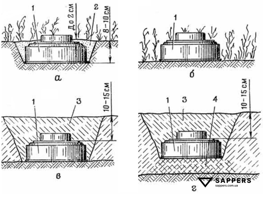
Camouflage of emplaced TM-72 mines is carried out using surrounding material (grass, leaves, etc.) or with a layer of soil up to 2 centimeters. Camouflaging the mine with a layer of soil more than 2 centimeters thick is not permitted, since this reduces the destructive effect of the mine. Camouflage with snow, in a layer up to 15 centimeters, has almost no effect on the armor-penetration capability of the mine. Mines emplaced in the ground (snow) are more resistant to the effects of the shock wave of a nuclear explosion and to line charges used for mine clearance.
To emplace the mine in the ground manually, it is necessary to (Fig. 7, a):
- Dig a recess 8-10 cm deep to the size of the mine body.
- Place the mine in the recess, and fill the voids around the side of the mine with soil; excess soil removed when digging the recess must be camouflaged separately in depressions in the terrain.
- Camouflage the mine by bending down grass, using leaves, dusting the mine body with a layer up to 2 centimeters, dust, or other local material matching the surrounding terrain.
- Switch the mine fuze to the armed position and adjust the camouflage.
To switch the MVN-72 fuze to the armed position, it is necessary to:
- Remove the seal and the wire cotter pin from the fuze.
- Raise the latch of the safety pin so that it disengages from the lug on the handle, and remove the safety pin.
- Raise the folding handle to the vertical position.
- Press the button in with the thumb until it stops.
- Lower the folding handle and camouflage the fuze from above (if necessary).
The safety pins and cotter pins are handed over to the squad leader.
Emplacement by dropping from a vehicle
Mines may be emplaced from vehicles by dropping, using chutes or manually. Depending on seasonal conditions, mines are emplaced in the ground (snow) with full camouflage (as are mines with pressure-action fuzes), in the ground with camouflage of the body only (Fig. 7, a), and on the surface of the ground (snow). When emplacing TM-62 series mines manually with full camouflage, the mine is camouflaged without creating a mound over the fuze.
Arming MVN-72 fuzes (in TM-62 series mines) is carried out only manually after the mine has been emplaced on the ground (according to the TM-72 emplacement procedure).
Emplacement of TM-62 series mines with the MVN-72 fuze from vehicles and manually along a mine-laying cord and by drill calculation is carried out in the same way as for the TM-72.
When emplacing mines on the ground surface by laying from a vehicle, arming of fuzes is carried out in each row by two combat engineers moving behind the vehicle. One combat engineer removes the seals, wire cotter pins, and safety pins from the fuze, and also raises the handles to the vertical position. The second combat engineer, following last, camouflages the mines, presses in the buttons, and lowers the handles to the armed position.
When emplacing mines in the ground by laying from a vehicle, arming of fuzes and camouflage is carried out in each row by one combat engineer, who moves behind the combat engineers engaged in placing the mines in the ground.
When emplacing mines manually along a mine-laying cord and by drill calculation, all emplacement and arming operations are carried out by one combat engineer.
Movement through the minefield is organized so that combat engineers pass armed mines at a distance of no less than 2 meters from the mine.
Emplacement using mine-laying vehicles
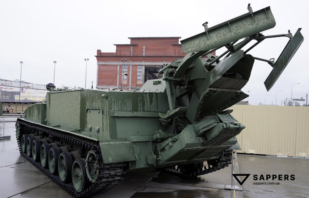
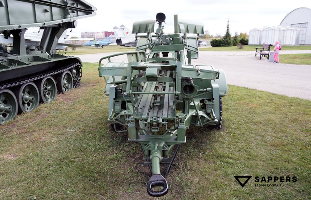
Minefields with TM-62 series mines fitted with the MVN-72 fuze may be emplaced using PMZ-4 (PMR-3) mine-laying vehicles (Fig. 8, bottom) or the GMZ-2 (Fig. 8, top). These mechanized means lay mines into the ground (snow) or onto the surface. Mines are loaded into the container of the PMZ-4 (PMR-3) and the GMZ-3 minelayer with safety pins installed. Seals, wire cotter pins, and mine handles are removed during loading. When laying mines using the PMZ-4 and PMR-3, their transfer mechanisms are raised to the non-operating position.
When emplacing TM-62 series mines with prior laying by the PMZ-3 minelayer, in order to obtain a spacing of 8 or 11 m, mines are fed into the chute at every second interval of the drive chain, and to obtain a spacing of 12 m, at every third interval of the drive chain.
When using GMZ-2 or PMR-3 minelayers, mines are laid in 2 rows with spacing of 4 or 5.5 m. To obtain spacing of 8 or 11 m, the mines are redistributed after laying into 4 rows.


Rendering safe
Mines with the MVN-72 fuze that are emplaced with the fuze camouflaged; that have a damaged fuze; or that are emplaced in an unstable position are prohibited from being rendered safe.
In cases of critical necessity, it is permitted to render safe mines with the MVN-72 fuze, but only if the upper part of the fuze is not camouflaged. Mines are usually searched for visually when rendering them safe. If visual detection of a mine is not possible (high dense grass), use of an IMP induction mine detector is permitted. Combat engineers carrying out mine searches and switching them to the transport position must not carry ferromagnetic objects (weapons, shovels, knives, steel probes, etc.). Their footwear must have no steel inserts.
To render safe a mine with the MVN-72 fuze, it is necessary to:
- Inspect the mine without touching it and ensure that: the fuze has no damage; there are no shell-crater explosions near the mine (closer than 1 m); there are no metal objects (fragments) on top of the mine; and the mine is in a stable position (if the condition of the mine does not meet these criteria, removal of such a mine is prohibited; it is destroyed in place).
- Holding the mine fuze with the left hand so that the fuze and mine cannot move from their position, with the right hand raise the folding handle on the fuze to the vertical position and turn it clockwise (the direction is indicated on the mine cover) until it stops; at this point the button must rise and a click will be heard (if the button does not rise when the handle is rotated, removal of such a mine is prohibited; it is destroyed in place).
- After the click, turn the handle in the opposite direction (counterclockwise) and fold it down into the horizontal position, into the recess in the fuze body.
- Install the safety pin under the button so that the pin latch “fits” with its hole over the lug on the folding handle, and secure the pin with the wire cotter pin (or thin wire).
- Remove the mine from the emplacement site and carry it to the designated location.
If the mines must be transferred to a depot, the MVN-72 fuzes are unscrewed from the mines. The power cells are removed from the fuzes. The mines and fuzes are placed separately in packaging and transferred to the depot.
For rendering safe mines with the MVN-72 fuze in a minefield (under safe conditions), the following organization of work is recommended. For mine search and switching fuzes to the transport position, a two-man team is assigned to each row.
The No. 1 of the team moves along the row and measures the mine spacing by pacing, searches for mines, raises and rotates the folding handles of the fuzes (winds the clockwork mechanism), thereby switching the fuzes to the safe position. In order for the following No. 2 to distinguish mines brought to the safe position, No. 1 does not rotate the folding handles back to the reverse position, but leaves them raised vertically.
No. 2, carrying safety pins, turns the handles in the opposite direction, folds them down into the horizontal position, installs the safety pins, secures them with wire cotter pins, and places the mines on edge.
A separate team is assigned for moving mines brought to the transport position.
It is prohibited, when switching fuzes to the transport position, to remove any steel objects from the mine or bring any steel objects to it. The metal safety pin is installed on the fuze only after it has been switched to the safe position (after the button has risen).
Mines removed from the minefield may be used for re-emplacement with replacement of the power cells with fresh ones.
Mines emplaced with full camouflage, if mine clearance is necessary, are destroyed by sweeping with electromagnetic mine rollers/trawls or by detonating placed charges.
It is prohibited to sweep mines with MVN-72 fuzes using track-width roller and blade mine plows, since mines that enter the inter-track space under the plow may fail to function but then detonate under the bottom of the tank.
Search for mines emplaced with full camouflage (when destroying them with placed charges) is carried out using the IMP mine detector.
It is prohibited to use a probe (even a non-steel one) to determine the exact location of an emplaced mine, since displacement of the mine from its position when pressed by the probe may cause the mine to function.
Detected mines are destroyed sequentially, one at a time, by explosions of placed charges with a mass of not less than 0.4 kg. The charge is placed on the camouflage layer or on the mine body next to the fuze (if the mine is emplaced without camouflage of the fuze). Detonation of the charge is carried out by electrical or non-electric ignition. For the non-electric method, ZTP igniter tubes with a friction igniter (Fig. 9) or tubes fabricated in the troops are used.
It is prohibited to use ZTP igniter tubes with mechanical igniters made of steel.