Technical and tactical characteristics of the PMN (PMN-1) mine
- Mine type
- Blast anti-personnel, with an arming-delay mechanism (metal element)
- Body
- Plastic/rubber
- Weight
- 0.55 kg
- Explosive weight
- 0.2 kg
- Explosive type
- TNT
- Diameter
- 110 mm
- Height
- 53 mm
- Target sensor diameter
- 100 mm
- Sensitivity
- 8-25 kg
- Operating temperature range
- -40 to +50 °C
- Method of emplacement
- Manual
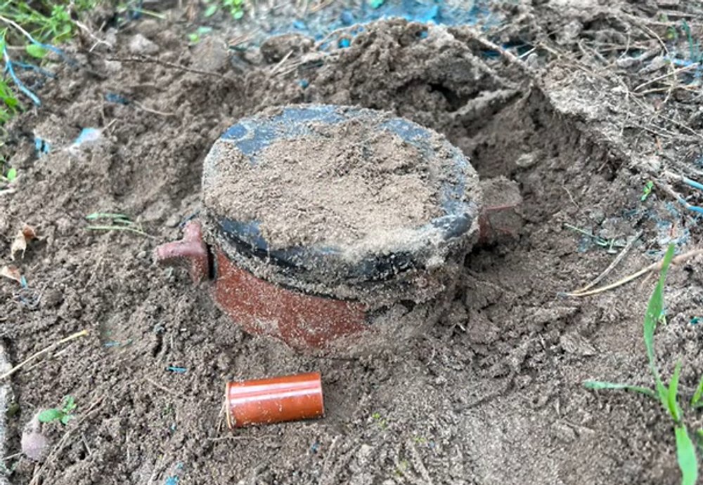
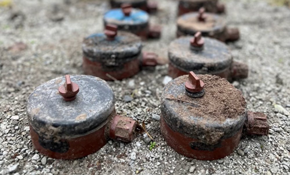
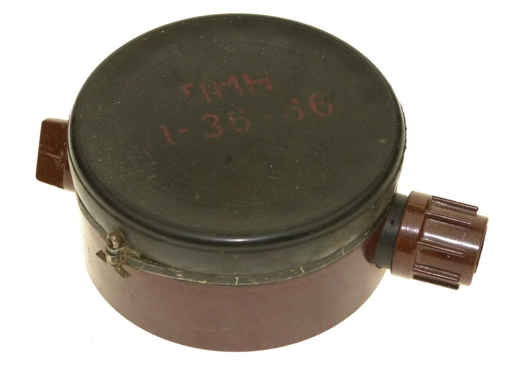
- Color
- Brown body with black cover
- Marking
- PMN - mine code;
11-36-66 - manufacturer plant code - batch number - year of manufacture (figures may vary)

Construction and principle of operation
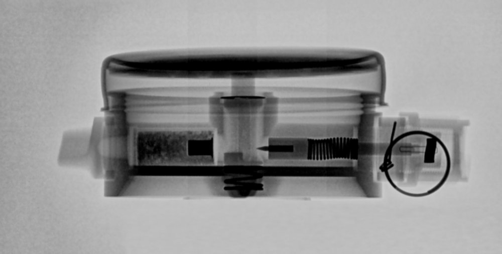
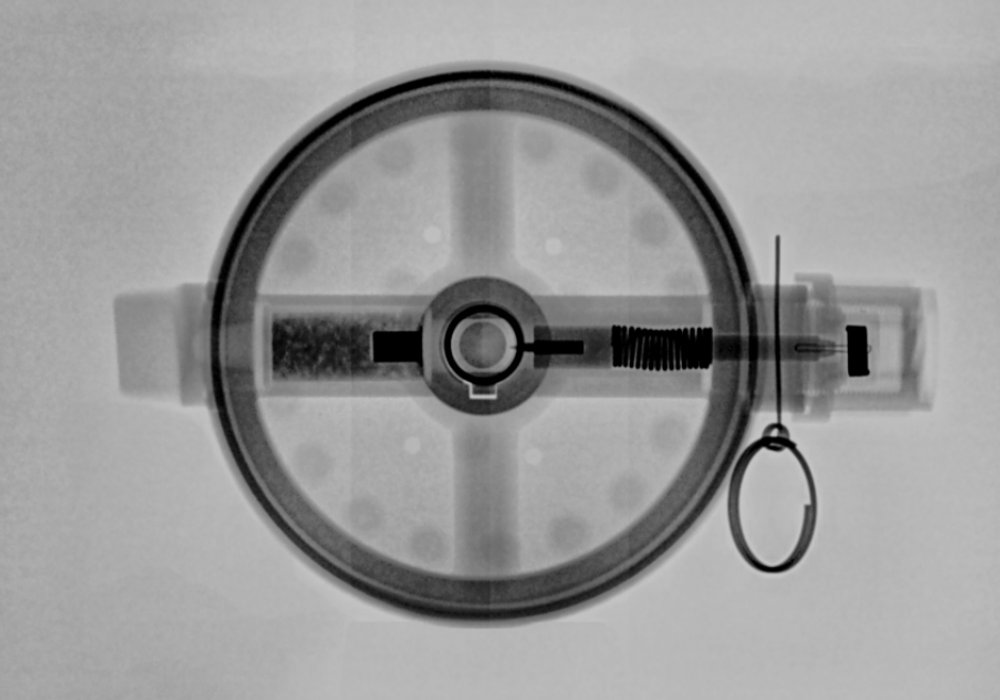
The PMN (PMN-1) mine consists of a plastic body, an explosive charge, a pressure device, release and striker mechanisms, as well as an MD-9 fuze.

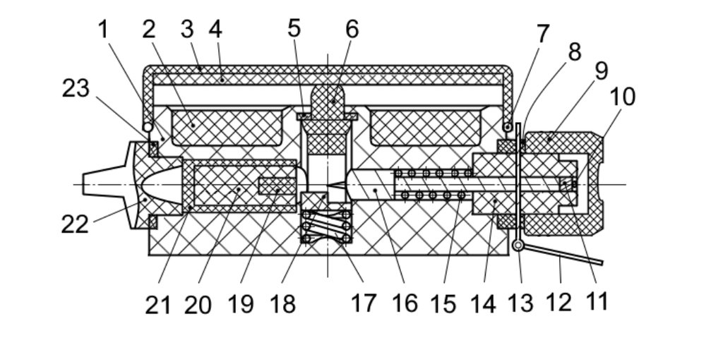
The mine body (pos. 1) has two channels: vertical and horizontal.
The explosive charge (pos. 2) is a special TNT block fixed in the body with lacquer.
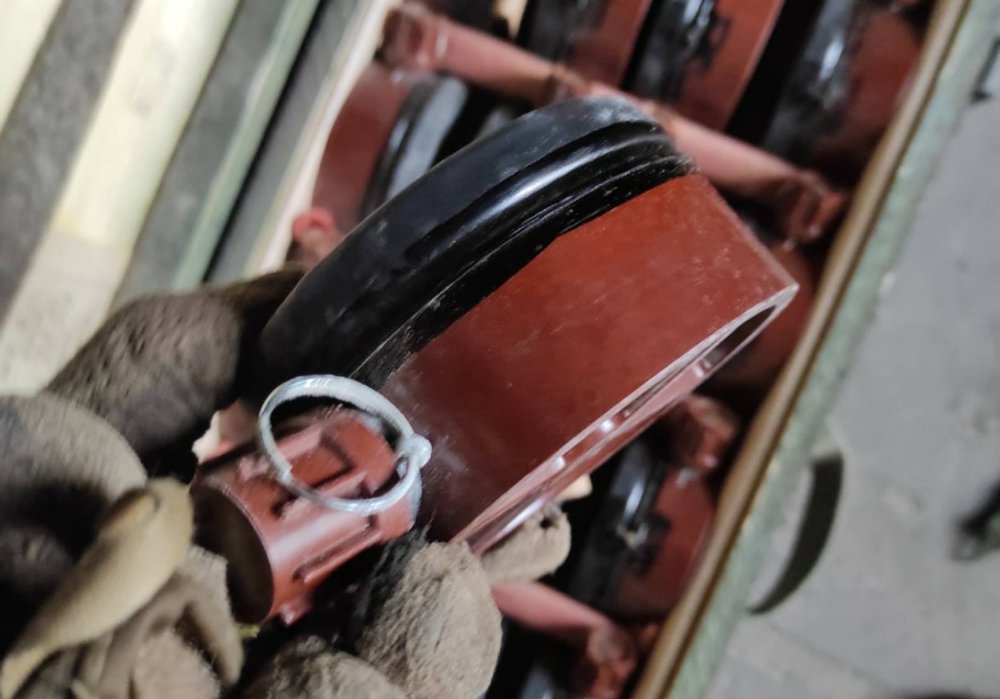
The mine pressure device (cover) consists of a rubber cap (pos. 3) and a plastic plate (pos. 4). The rubber cap is fitted onto the body and secured with a metal band (pos. 7).
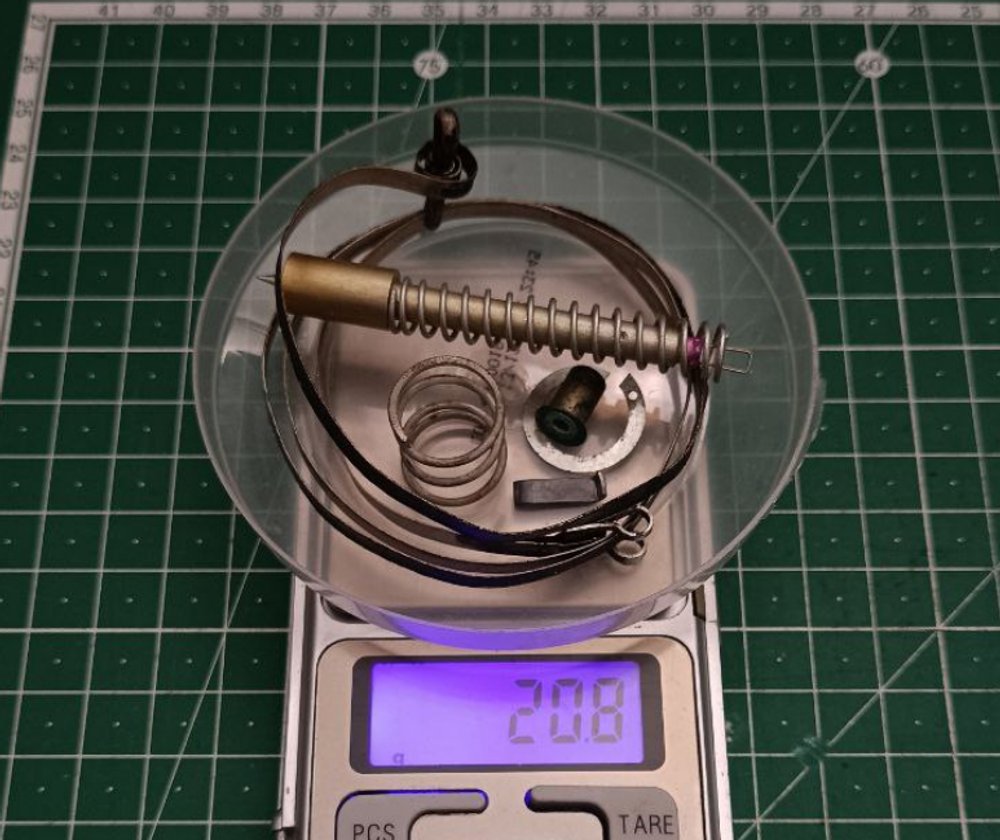
The release mechanism is installed in the vertical channel of the body. It consists of a plastic plunger (pos. 6), a spring (pos. 17), and a split ring (pos. 5). The plunger has an aperture with a cocking lug (pos. 18). When the mine functions, the striker passes through the aperture in the plunger. After the metal element is cut, the cocking lug holds the striker in the cocked position. In the assembled mine, the plunger is pressed upward by the spring (pos. 17) against the split ring.
The striker mechanism is located in the horizontal channel of the body. It is assembled as a separate unit and has an arming-delay mechanism. The striker mechanism consists of: a sleeve (pos. 14), a striker (pos. 16) with a cutter (pos. 10) in the form of a steel loop (secured by means of an insert), a striker spring (pos. 15), metal element No. 2 (pos. 11), a safety pin (pos. 13) with a ring (pos. 12), a cap (pos. 9) with a rubber gasket (pos. 8) (which seal the joint between the striker mechanism and the mine body.
In PMN (PMN-1) mines manufactured before 1965, the cutter has a different design. It was made as a piece of steel wire secured in a metal frame at the end of the striker stem.
In the assembled striker mechanism, the striker spring is compressed, the striker stem passes through the sleeve and is held in it by the safety pin. Metal element No. 2 is located in the groove of the sleeve within the cutter loop.
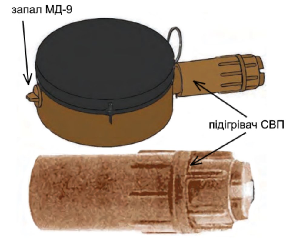
The MD-9 fuze is located in the horizontal channel of the body, on the side opposite the striker mechanism. The fuze itself consists of a plastic case (pos. 21), a 6.5 g tetryl pellet (pos. 20), and an M-1 stab-action detonator cap (pos. 19), fixed in the pellet recess with lacquer. The tetryl pellet serves as a booster charge. The MD-9 fuze is secured in the mine by a plug (pos. 22) with a rubber gasket (pos. 23).

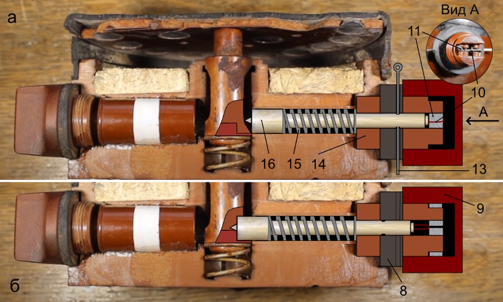
After the safety pin is withdrawn, the arming-delay mechanism functions (metal element No. 2 is cut). The mine assumes the armed position — the striker rests against the cocking lug of the plunger. When pressure is applied to the mine cover, the plunger moves downward, and the cocking lug of the plunger disengages from the striker. The striker is released, passes through the aperture in the plunger under the action of the striker spring, and strikes the M-1 detonator cap. This initiates the detonation of the tetryl pellet and the mine explosive charge. The mine’s operational life in the armed state is unlimited.

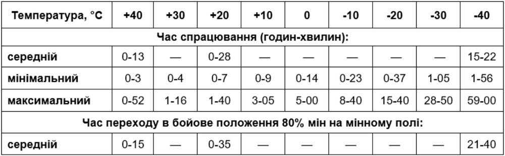
The mine may also be fitted with an SVP metal-element stabilizer (heater). The heater is installed on the mine’s striker mechanism. This is done to offset the effect of external temperature on the arming-delay mechanism. The heat from combustion of the SVP pyrotechnic composition makes it possible to stabilize the arming-delay functioning time to 60-140 sec (depending on ambient temperature).

Preparation and emplacement
To prepare the mine, it is necessary to:
- unscrew the cap from the sleeve of the striker mechanism and check the condition of the cutter and the presence of the metal element.
- screw the cap back into place.
- unscrew the plug, install the MD-9 fuze in the mine, and tighten the plug fully.
Mines may be prepared in cover immediately before moving out for mine-laying. Mines fitted with MD-9 fuzes are carried to the emplacement site in kit bags.
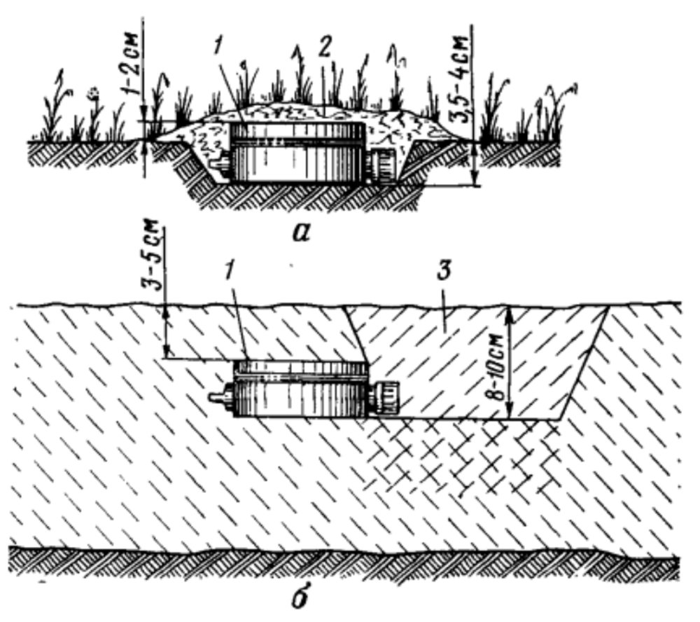
In summer conditions (as well as in thawed soil), mines are emplaced in the ground (a) with the cover raised 1-2 cm above the ground surface and camouflaged with grass, leaves, soil, etc.
In winter, if loose snow is present, mines are emplaced in the snow and camouflaged with a 3-5 cm layer of loose snow (b). In hard, compacted snow (ice), mines are emplaced in the same way as in the ground.
In frozen and very hard (rocky) ground, mines are emplaced on the surface and camouflaged with surrounding materials.
To emplace the mine in soil (hard snow), it is necessary to (a):
- Dig a hole to the dimensions of the mine (pos. 1), 3.5-4 cm deep;
- Place the mine in the hole and, while holding it by the cap with the hand without pressing on the cover, withdraw the safety pin and turn the cap;
- Camouflage the mine (pos. 2).
Emplacement of the mine in loose snow (b):
- Make a hole in the snow with the foot (pos. 3), near the intended emplacement site of the mine, 8-10 cm deep.
- Without pressing on the cover, withdraw the safety pin and turn the cap by hand force.
- Holding the mine by the cap with the hand, place the mine (pos. 1) under the snow through the side wall of the hole, without disturbing the snow layer above the mine.
- Camouflage the hole in the snow through which the mine was emplaced, without disturbing the snow layer around the mine.

PMN (PMN-1) mines may be laid on the surface from cargo trucks or by the PMZ-4P towed mine layer (with additional equipment). Emplacement of mines in the ground, placing them into the armed position, and camouflaging are carried out only manually.

Render-safe procedures
Rendering PMN (PMN-1) mines safe is prohibited. The mine may be fitted with an ENO-PMN anti-handling device, externally similar to the SVP. The mine is not equipped with a self-destruct mechanism. It does not have standard anti-lift elements.
It is destroyed at its emplacement site by detonating explosive charges placed next to the mine.