Technical and Tactical Characteristics of the PMN-2 Mine
- Type of mine
- anti-personnel blast mine, pressure-actuated, fully assembled
- Body
- plastic
- Weight
- 0.4 kg
- Explosive weight
- 0.1 kg
- Type of explosive
- TG-40
- Diameter
- 120 mm
- Height
- 54 mm
- Type of fuze
- mechanical, integral, with arming-delay mechanism
- Type of arming-delay mechanism
- pneumatic
- Arming delay time
- 30-300 s
- Target sensor diameter
- 97 mm
- Sensitivity
- 5-25 kgf
- Operating temperature range
- -40 to +50 °C
- Method of emplacement
- manually or by PMZ-4P mine layer
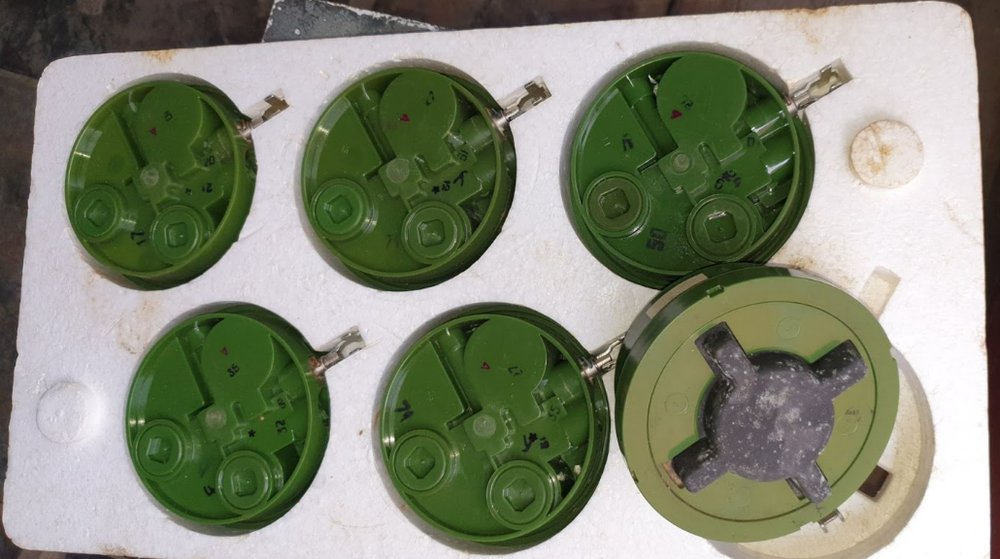
- Color
- green, dark green, brown with a black crosspiece
- Marking appearance
- black, applied to the side wall of the mine
- Marking
- PMN-2 - mine code;
42-M-41-81 - manufacturer plant code - lot number - year of manufacture;
TG-40 - explosive
Detonation of the mine (when the target sensor is stepped on) results in traumatic amputation of the lower part of the leg, as well as probable blast injury to the other leg. During the explosion, a person may sustain associated injuries such as concussion, burns from explosive gases, injuries from secondary fragments, etc. In the absence of timely pre-hospital care, death occurs as a result of critical bleeding.

Design and Operating Principle
The PMN-2 mine consists of a body, charge, pressure sensor, and an integral fuze with a pneumatic arming-delay mechanism. The body (item 1) is plastic, with compartments for the charge and arming-delay mechanism; one vertical and two horizontal channels for accommodating the fuze mechanisms. The body is closed on top by a cover (item 2).
The TG-40 charge (item 13) has an additional tetryl detonator (item 15), weighing 4.5 g
The pressure sensor consists of a spring-loaded stem (item 12) located in the vertical channel of the body. The crosspiece (item 3) rests on the stem and is covered by a rubber cap (item 4), secured on top of the body by a union nut (item 5).
The integral safety-type fuze ensures interruption of the mine’s firing train (in the transport position), arming into the combat position with a delay of 30-300 s, and detonation of the mine charge when pressure is applied to it (in the combat position). The fuze consists of a pneumatic arming-delay mechanism, a spring-loaded slider (item 17) with a detonator cap, and a striker (item 14) with a striker spring.

The arming-delay mechanism consists of a bellows (item 6) and a spring-loaded bushing (item 7) with a diaphragm. The bushing, by means of its tooth (item 16), holds the slider (item 17) in the transport position. The detonator cap is offset from the striker and the auxiliary detonator; the bellows (item 6) is filled with air. The bushing (item 7) is in the lower position, compresses the spring (item 8), and is held in this position by the stem (item 11), connected by a lock to the safety pin (item 9), which is secured by the shear pin (item 10).
The striker compresses the striker spring and is held in the armed position by the stem (item 12) of the pressure sensor.
When the safety pin (item 9) is turned, the pin (item 10) is sheared, and when the safety pin is pulled out, the stem (item 11) is displaced, releasing the bushing (item 7). The bushing, under the action of the spring (item 8), then moves upward. The bellows (item 6) is compressed, and air is expelled from it through the opening in the diaphragm. After 30-300 s, the tooth (item 16) of the bushing releases the slider (item 17), which, under the action of the spring, moves into the combat position; that is, the detonator cap is positioned opposite the striker and the auxiliary detonator.
When pressure is applied to the target sensor, the crosspiece presses on the stem (item 12). The stem moves downward and releases the striker (item 14). The striker, under the action of the striker spring, strikes the detonator cap, which detonates and initiates the detonation of the auxiliary detonator and the mine charge.


The mine body may be green, dark green, or brown, with a black crosspiece.

Preparation and Emplacement
PMN-2 mines are emplaced:
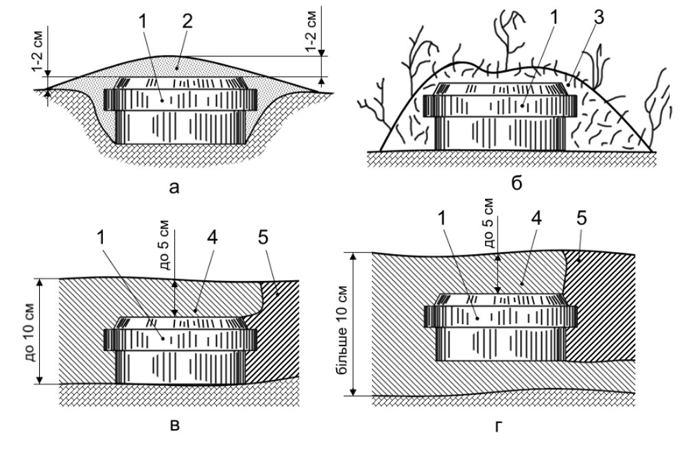
- In summer, in the ground or on the ground surface, camouflaged with soil or vegetation
- In winter, on the ground surface or in snow, camouflaged with snow.
In winter, when the snow depth is up to 10 cm, the mine is placed on the ground surface. If the snow depth exceeds 10 cm, the mine is placed in the snow.
In hard compacted snow, mines are emplaced in the same manner as in soil.

Manual emplacement of mines in the ground is carried out in the following sequence:
- Dig a recess to the diameter of the mine, 3-4 cm deep.
- Place the mine in the recess.
- Turn and pull out the safety pin.
- Camouflage the mine.
Manual emplacement of mines in deep snow is carried out in the following sequence:
- Press out a recess in the snow.
- Turn and pull out the safety pin.
- Push it under the snow so that the camouflage layer above it is no more than 5 cm.
- Camouflage the recess with loose snow.
Emplacement of mines using the PMZ-4P mine layer (with additional equipment for laying anti-personnel mines) is carried out in the following sequence:
- Mines are removed from their packaging and placed in the magazine.
- From the magazine, the mines are fed into the chute.
- Sappers (two personnel), moving behind the mine layer, dig recesses and emplace the laid-out mines in them.
- One sapper, moving last, arms the mines and camouflages them.

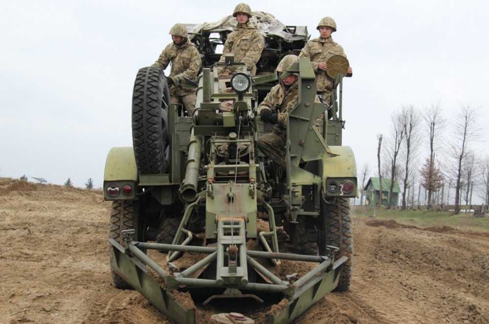
Mines may also be emplaced by dropping them from a vehicle. Three to four personnel are assigned to the vehicle; they unpack the mines, turn and pull out the safety pins, and drop the mines over the side of the vehicle. To obtain a three-row minefield, mines are dropped to the left, to the right, and to the rear in the direction of vehicle movement. Mines emplaced with the target sensor facing downward retain their functionality.

Disposal
Disarming PMN-2 mines is prohibited.
Emplaced mines are destroyed by:
- Detonation of a 0.2 kg explosive charge placed next to the mine.
- Repeated passes over the minefield by a tank with a mine roller (towed rollers) or without mine rollers (by track).
Reliable initiation of mines when tanks pass over them is ensured only on level terrain.