Technical and Tactical Characteristics of the PMN-4 Mine
- Mine type
- blast mine with a pressure-actuated fuze
- Mine weight
- 0.3 kg
- Weight of explosive charge
- 0.05 kg
- Type of explosive
- TNT
- Weight of packaging with mines
- 28 kg
- Overall dimensions of the mine (diameter x height)
- 95x42 mm
- Overall dimensions of the packaging
- 658x598x200 mm
- Arming delay time
- 1-40 min (depending on ambient temperature)
- Mine fuze actuation force
- 5-15 kgf
- Safety pin pull force
- 5 kgf
- Case material
- plastic
- Operating temperature range
- -40 to +50 °C
- Operational service life in a minefield
- 1 year
- Time to emplace one mine with a 2 cm camouflage layer
- 1.5-2 min
- Number of mines per package
- 40 pcs
- Guaranteed storage life
- 10 years

Design and Purpose of Mine Components
The mine consists of a case, an explosive charge (TNT), and an integral fuze.
The case (item 1) is a plastic cylindrical body with cavities for accommodating the explosive charge and fuze mechanisms. The case is sealed and closed on top with a rubber cap (item 2), which is secured to it by means of a steel clamp.
The explosive charge (item 3) is a pressed TNT block in the form of a ring, located in the cavity of the case under the cover (item 14).
The integral fuze consists of a pressure target sensor, an arming delay mechanism, a safety-and-firing mechanism, and a safety pin.
The pressure target sensor consists of a rod (item 4), a spring (item 5), and a crosspiece (item 6)
The arming delay mechanism consists of two rods (items 8 and 9), a spring (item 7), and rubber (item 10), located in a cylindrical housing.

1 - case; 2 - rubber cap; 3 - explosive charge; 4 - rod; 5 - spring; 6 - crosspieces; 7 - spring; 8 - rod; 9 - rod; 10 - rubber; 11 - safety-and-firing mechanism sleeve; 12 - safety cap; 13 - cable; 14 - cover.
The safety-and-firing mechanism consists of a slider (item 3) with a KD-N-10 detonator cap (item 4), a spring (item 2), a stop bracket (item 1), a stop (item 6), and a striker (item 5) with a spring. In the transport position, the detonator cap is offset relative to the axis of the striker (item 5) and the detonator (item 7). The detonator is a PETN explosive pellet weighing 3 g, pressed into a cap with a cup.
The safety pin is a flexible metal cable (item 11) connected to a safety cap (item 10), which is fitted onto the mine case. The cable is wound onto the sleeve of the safety-and-firing mechanism.
In 1989-1990, the mines were manufactured with a bracket attached to the mine case.


For the establishment of simulated minefields during training tasks, there is a practice version of the mine. In design, the practice mine is analogous to the service mine, but it has an inert charge and detonator, and a practice fuze in whose firing train a KVN-1 primer is used instead of the KD-N-10 detonator cap.
For training personnel and practicing standards for the emplacement of individual mines and minefields, there is a training version of the mine. In design, the training mine is analogous to the service mine, but it has an inert charge and detonator and has no detonator cap in the firing train.

Operating Principle
The mine is transferred from the transport position to the combat position after the safety pin is pulled. When the safety pin is pulled, the sleeve (item 11) rotates and shifts, thereby releasing the rods of the arming delay mechanism (items 8 and 9). The rods of the arming delay mechanism rise under spring pressure, during which the rubber flows through the annular slot of the piston from the upper cavity into the lower cavity. The slider with the KD-N-10 detonator cap (item 4), under the action of the spring (item 2), rotates the stop (item 6) and assumes a position coaxial with the striker (item 5) and the detonator (item 7). The striker is retained by the lug of the target sensor rod (item 8). The mine has been transferred to the combat position.
When pressure is applied to the crosspiece of the target sensor (item 9), the rod (item 13) rises and releases the striker (item 5), which moves under spring force and strikes the detonator cap. The detonator cap, the detonator, and the explosive charge detonate.

Safety Measures
It is prohibited to:
- Press on the target sensor after the safety pin has been pulled.
- Emplace mines that are damaged or have a pulled safety pin.
- Transport boxes of mines by air without puncturing the polyethylene packaging.
- Store and transport unpacked mines by any mode of transport.
All operations during mine emplacement after the safety pin has been pulled must be completed in less than 30 seconds.
Preparation for Emplacement and Emplacement
The mine may be emplaced:
- On the ground surface.
- In the ground with a 2 cm camouflage layer of soil.
- In snow with a 20 cm camouflage layer of snow.
- In a ford up to 50 cm deep.
The mine is emplaced manually or from a vehicle (via chutes or by dropping over the side).
Before emplacing the mine, it is necessary to check for the absence of mechanical damage and the presence of the safety pin.
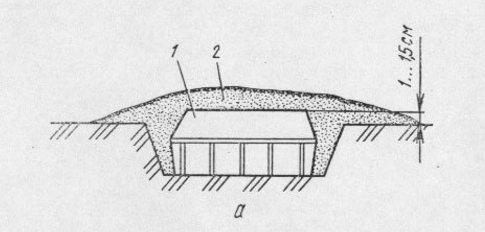
To emplace the mine in the ground (Fig. a) manually, it is necessary to:
- Dig a recess 3-3.5 cm deep.
- Place the mine in the recess.
- While holding the mine by its side surface with one hand, use the other hand to release the safety cap from the latches and lift it.
- Pull out the safety cap together with the cable.
- Camouflage the mine and the emplacement site.
In areas with vegetation that can conceal the mine, the mine may be emplaced on the ground surface.
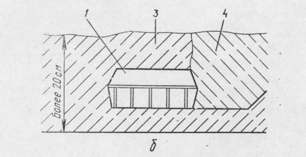
In winter, when the snow depth is up to 20 cm, the mine is emplaced on the ground; at greater depths, it is emplaced on compacted snow (Fig. b).


Mine Neutralization
Mines emplaced in the field in the combat position are prohibited from being removed or neutralized!
Mines are destroyed by detonation of a 0.2 kg explosive charge placed next to the mine or by repeated passage of armored vehicles with mine rollers over the minefield.
Marking
Markings on the mines and packaging are applied in black paint.
The following are applied to the lower end surface of the mine:
- Mine index.
- Manufacturer's code designation.
- Batch number and year of manufacture.
An additional red stripe is applied to the lower end surface of the practice mine.
The following are applied to the box containing mines:
- Cargo hazard label, which contains: hazard symbol (exploding bomb), inscription "Взрывается", classification code - 1.1F, class - 1.
- Index of the mines and their quantity
- Manufacturer's code designation, batch number, and year of manufacture.
- Explosive code.
- Inscription "Перед авиаперевозкой булавкой проколоть пакет через отверствие".
- Gross weight.
- On the lid of the box, the conditional number of the dangerous goods in a triangle - 153.
The following are applied to the box containing practice mines:
- Cargo hazard label, which contains: subdivision - 1.4, compatibility group - F, class - 1.
- Classification code - 1.4F.
- Index of the mines and their quantity.
- Manufacturer's code designation, batch number, and year of manufacture.
- Explosive code.
- Inscription "Перед авиаперевозкой булавкой проколоть пакет через отверствие".
- Gross weight.
- On the lid of the box, the conditional number of the dangerous goods in a triangle - 430 and a red stripe.
A label is affixed to the inner side of the box lid.
A packing list and instructions for use are placed in each box on the lid side.
Packaging
The mines are packed in wooden boxes. The boxes contain 4 blocks of polystyrene inserts (2 inserts per block), placed in a sealed polyethylene bag. Each block contains 10 mines. A total of 40 mines are placed in the box.
A pin for puncturing (depressurizing) the polyethylene bag through an opening in the box before transporting the mines by air is attached to the front wall of each box.